

The Design Process: YZ-F Intake Scoop Case Study
Since we used a lot of unique technologies when creating our latest intake scoop offering, we thought it might be of interest to share a bit about the process for those interested in the product development space and give a glimpse into what is involved in bringing a relatively simple product to market. While our smaller scoop was already popular, one bit of feedback we consistently got was “go bigger!”, so we did! Increasing the volume of the scoop also required it to cover more surface area on the airbox cover, which is where the challenge began. Anyone who has seen the latest generation Yamaha airbox covers knows that there is absolutely no flat surface to be found, with every inch being some sort of strange, complex curve that defies simple definition. While it may be possible to iterate the design with trial and error in CAD to get a close fit, we felt that this would be both inefficient and extremely wasteful of material while likely never producing a truly perfect result.

Getting to a finished product is a longer process then most people realize
The easiest approach seemed to be to have the cover 3D scanned and then imported into our CAD program (we use Fusion 360 but this can be done with almost any program in a similar fashion). The idea was that we would be able to first create the 3d model of the scoop slightly larger than it would be in real life, then use a Boolean Operation within Fusion 360 to subtract the intake cover out of the scoop and be left with a perfect fit to the cover surface. We had a bit of experience with 3D scanning in the past with great results, so we sent a new OEM cover down to our friends at Tangent Solutions to have them work their magic with a blue light scanner. Without getting too far into the weeds, a blue light scanner essentially projects a laser pattern onto an object, and a camera takes note of how the patterns behave on the surface. Since the location of the camera and laser projectors is known, triangulation can be used to determine the precise geometry of the part being scanned and create a detailed 3D model. The first half of the video below gives a good overview of the process:
https://www.youtube.com/watch?v=IHOrPD1nC-o
Once the scan was complete we received our STL file of the intake cover. The issue with the native STL file format is that it is not an editable file, essentially it is good for visualization and 3D printing but not much else. Because of this Tangent Solutions also offers a service to translate the part into an editable STEP file, however we chose to save a bit of cost and perform this ourselves within Fusion 360 since this is a relatively simple part. In hind sight this proved to be a bit more of a challenge than we anticipated, but we did learn a lot about the process along the way. Because we were really only concerned with the top surface of the part, we focused only on this area and created a new surface using the scanned STL file as a guide. Fusion 360 allows you to define an area over which you would like to create a new surface, then select reference points from the STL model to “pull” the surface over the model and follow its contours. Think of it like taking a flat blanket, then draping it over a surface covered in adhesive. The blanket will at first be flat, but as you let it rest over the surface it will begin to take its shape and be manipulated around the contours until you have essentially created a shell over the surface. We are performing the same operation within Fusion, however instead of a blanket we are using a flat surface of zero thickness. There is a balance here when performing this process, too few reference points will create a model that is not detailed enough and deviates too far from the original scan, and too many data points will be redundant and create a bogged down model that will tax computing power and effect performance. The surface modeling steps can be seen in the photos below:

Native STL files straight from the 3D scan


Surface model “pulled” over the STL model using reference points
Now, clearly the new surface model is not perfect over most of the cover, but we are really only concerned with the top surface where the scoop will sit so this will be sufficient. We could, in theory, get more accuracy over the entire cover, but we run into that wall of slower performance that yields no benefit for this application. With this surface model we can now create the model of the scoop and subtract it away to create the final model. We won’t go into the boring details of each CAD step, but for a design like this it essentially consists of a lot of trial and error while trying to digitize a vision. You can see the process of subtracting the surface away from the scoop model in the photos below:

A rough initial model of the scoop, used to illustrate the surface splitting technique

Here we used the surface we created to split the scoop body, subtracting away the lower section.

We are now left with the geometry of the intake cover cut into the lower surface of the scoop.
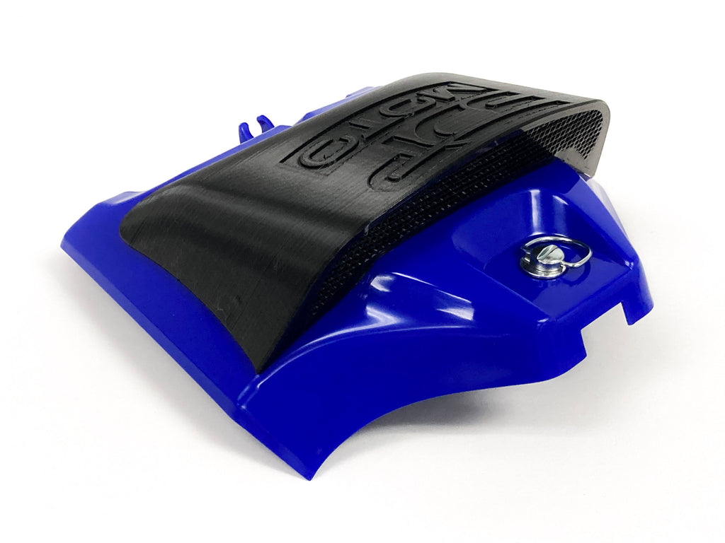
With the cutting operation done, additional refining of the model is performed and eventually we are left with the finished scoop! As you can see from the images below, the geometry of the airbox cover has been left on the bottom of the scoop, ensuring that the actual printed part will have a snug fit to the cover when it comes time to assemble the physical product.


The finished scoop model, ready for printing!
With the model completed, the final step is to create the tool path for the CNC routing table to cut the opening into the intake covers themselves. To complete this we can call upon an old friend of ours: the lower section of the scoop model we just subtracted away. Remember, this section will still have the same upper surface of the airbox cover, so we can use this as a guide for the toolpath. The process of creating the toolpath is relatively straight forward within Fusion 360, and this particular application yields a simple operation:

The simple toolpath generated to cut the opening in the intake cover.
We hope this provided a bit of insight into the design process necessary to bring this relatively simple product to market. While experienced designers are likely scoffing at the simplicity, we felt that this would provide an easy case study for those who are not familiar with the process and hopefully provide a little information about the various steps necessary. Thanks for reading, and if you have any questions or comments please don’t hesitate to email us at info@3dpmoto.com!